Monday 30 March 2015

3ds--max bump map tutorial

 3ds max bump map tutorial


                                                 In 3ds max we always recommended the quality of render image like as a real click.which include reflection, refraction,sun light,shadow etc. but in all these we forget a recommended map. -BUMP MAP

bump map give us such depth type of effect and irregular surface. we also create depth our object from other reference like texture or any type of bitmap image. today we learn how can render with bump map.


render scene without bump map

first of all, we hit 'M' for open material editor.in MAP tab click on BUMP and give its amount.here lower amount give smooth and less depth and higher amount give sharp and huge depth to object when render.now click on NONE button. this button is a sub map. like telling us which map or texture/image want to bump on object.i click on map^standard^bitmap. (as shown in image) and simply select bitmap file from my library.

bump map setting


render with BUMP map- AMOUNT 30

                                                       ........as same as we also create any image or texture bumping on our object with bump mapping. if image need more depth we require to change setting 30 to increase amount till better image shown..... 

................enjoy tutorial
                           'have a nice day'


Saturday 28 March 2015

3ds max- pro boolean tutorial

3DS MAX -PRO BOOLEAN TUTORIAL


hiiiii friends,
Reverse pro boolean process


Difference between boolean and pro boolean is pro boolean is offering multiple subtract.

Object and only boolean tool subtract only one object when you  try to select second object for subtracting first object appear automatic. so, Pro boolean tools is more effective.


Today we learn how can subtract an object in 3d studio max.
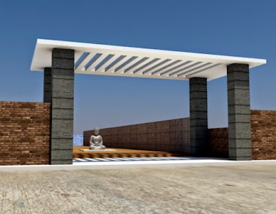
 An engineer or a designer usually put pergola design , wall subtracted design in parapet and compound wall etc. This time we require this tool.Called proboolean.

First, i create simply a scene


Now i want to get some pergola type design because my roof is like a plane box.
I have to create first object which i will subtract.


I select my roof object and go to drop-down list from control panel-standard primitives and select compound object.
(image shown bellow)


.
From compound object menu i select pro boolean (must be select object)...here you find same two type tool only boolean and proboolean. well we will get know the difference between above two tools later...

After the select pro boolean tool in pick boolean tab select start picking the object one by one which will i want to subtract from roof object.


Finally i create pergola design from using pro boolean tool.
I also change this operation reverse by select object from view port next select object in parameter list which is already subtracted and click on extract selected. 


after render the scene.


You can also use this tool in elevation design , parapet design and different type of uses.
Keep learning......and make it easy.


Friday 27 March 2015

3ds max-Tile map tutorial


3DS MAX-TILE MAP TUTORIAL


In exterior rendering we require sometime material like bricks, grooves and etc.Many time we have texture but not suitable color or design we actual want...here 3ds max give us TILE map for texturing like as bricks and many type of grooves design.... 


First, i create simple scene.

without apply tile map

Now i simply applying tile map from standard map-tiles ( image shown bellow)


O.K.

Now i see simply give tile map to my object. you can also 
modify tiling from standard control-pattern setup
like...

1.Custom tile
2.Running bond
3.Common Flemish bond
4. English bond
5.1/2 running bond
6.Stack bond
7.Fine running bond
8.Fine stack bond

Above list has different types tiling. you may practice and  learn how can 
create different type pattern.

Sometime we have groove texture but we have not different type color of groove texture. in that case tile map is very useful map. it also create different type grooves and its color.let's see how can do it....


In advance control select pattern setup -stack bond


In tile setup
Select texture color which is simply like wall color.You can also give it texture from our library like wooden, marble, dust, rust etc...
When we require single vertical or horizontal line, less the amount of hori. count or verti. count.

in grout setup
Select groove(grout) color. this is line color which is expose over wall color or selected texture.Many time we require more thickness in grooves so tile map give us extra setting of hori. gap and verti gap. Play with this setting, result more thickness to line.....

RENDER IMAGE AND ITS SETTINGS


Setting- 
tile setup-wooden texture
hori.count-1
verti count.-4
grout setup-black color
hori.gap-0.5
verti gap-0.5


Enjoy the tutorial.... :)


Sunday 22 March 2015

Lathe modifier-3ds max tutorial

hiiiii friends,


                Many time we need to create object manually like flower pot, glass some types of interior objects in our scene.that time we suffer to find out this type of objects and many time  we create that with very hard work....so i hope this tutorial give you solution and make it easy . :)

                 3ds max software provide us many types of modifier.when we need to some critical and different type of objects we create it with lathe modifier. today i learn u lathe modifier which is my favorite modifier.


Software-3ds max ( any older version)
Plug in-Default scanline render


First, We need to create a half shape which is likely match with our thinking.So i set a scene with simple box and in front view i create a temporary shape from shape tab in command panel. If i want to line corner change to smooth, select line and click on line from modifier now we see the vertex point at every corner point. Select the vertex point and right click. In this menu select the smooth option for change vertex point corner to smooth.

Create a shape


Now i am going to convert this shape to solid form so i apply Lathe Modifier from modifier list.
Lathe modifier lathing the shape in round.

After applying 'Lathe Modifier'

Now i see my shape convert into solid but this is not likely a full solid of my half shape....

Degrees-
in parameters i can change the value of degrees 360 degrees mean my shape lathing with full round i can adjust this amount as per my object.

Segments-
we know that less value of  segment make a sharply solid so i increase the value of segment 72 now i see in view port that my object convert sharp to smoother. i can change segment value more for smoothing object but remember that increase the segment value increase the file size,rendering time 
and need more graphics memory.

Align-
align tab has three option min-center-max.
I always align the object with minimum option. because minimum means modifier lathing the object from center to all side same and give result in best round shape.


After setting with Degrees and Align


Now i complete my all setting for looking object good and smooth.


Render Scene


Enjoy tutorials.....